
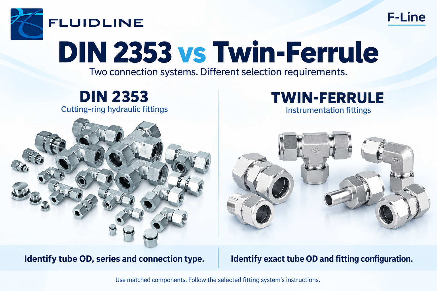
DIN 2353 cutting-ring fittings and twin-ferrule instrumentation fittings are different connection systems. Both can be suitable for demanding fluid applications when correctly specified, but their components, identification and tubing requirements must be checked separately. Choose around the application and the approved system, rather than appearance alone.
This distinction matters when replacing an existing fitting or putting together a new tube package. A nut that appears to fit a thread is not proof that the tube end, ring or ferrules will seal and retain the tube correctly.
What a DIN 2353 connection describes
DIN 2353 is a familiar designation used for metric hydraulic tube fittings associated with the 24° cone connection family covered by ISO 8434-1. A conventional cutting-ring assembly uses a fitting body, nut and cutting ring to connect the tube. Other connection designs exist within the wider 24° family, so the exact catalogue description remains important.
Identify the tube OD and fitting series, such as L or S, as well as the connection type. L and S are series designations, not universal pressure ratings. The permissible operating conditions depend on the particular fitting, tube, material, seals and service.
What a twin-ferrule connection describes
A twin-ferrule fitting uses a body, nut and two ferrules designed to work together around the tube. Uni-Lok offers this connection type for instrumentation systems in metric and fractional sizes. Selection must follow the requirements for that specific fitting range.
Applications can include instrument lines, sampling systems and process connections. Application labels are a starting point, however: calling a line “instrumentation” or “hydraulic” does not replace checking its actual pressure, temperature, medium and mechanical conditions.
Compare the selection requirements
| Selection point | DIN 2353 cutting-ring system | Twin-ferrule system |
|---|---|---|
| Tube connection | Typically a metric tube with a cutting ring and 24° cone body. | Tube retained and sealed by a matched pair of ferrules. |
| Size identification | Tube OD, series and exact fitting configuration. | Exact metric or fractional tube OD and fitting configuration. |
| Tube selection | Use the tube condition and dimensions required by the selected cutting-ring system. | Use the hardness, surface condition and wall range specified for the selected ferrule system. |
| Pressure assessment | Check the specific assembly and operating conditions. | Check the specific assembly and operating conditions. |
| Installation | Follow the relevant preparation, assembly and inspection instructions. | Follow the relevant assembly and inspection instructions for that size and range. |
Four checks before ordering a replacement
First, establish what is already installed from the drawing, part number, markings and dimensions. Photographs help, but a photograph alone may not identify the thread or sealing arrangement.
Second, measure the tube OD accurately. For example, 12 mm and ½ inch are not equivalent. Also distinguish the tube connection from the equipment port: a fitting may have a metric tube end and a different thread system at the other end.
Third, confirm the service conditions and the approved component family. Include any elastomer seals, temperature limits and vibration considerations in the review.
Fourth, order the appropriate complete assembly or approved spare components. Treat nuts, rings, ferrules and bodies as parts of a matched system. Confirm compatibility before mixing manufacturers or designs.
Frequently asked questions
Can a DIN cutting ring replace twin ferrules?
No. These are different connection designs. Use the components specified for the selected fitting system.
Is one system always rated for a higher pressure?
No. Compare the published ratings and restrictions for the exact assemblies at the required temperature. The family name alone does not establish the allowable system pressure.
Can different fitting systems be connected in one installation?
Where the design requires a transition, use a suitable rated adaptor with the correct connection at each end. That is different from combining mismatched internal components.
Send the connection details to Fluidline
For help identifying an appropriate fitting, send the tube OD and wall thickness, series if known, port details, service conditions and clear photographs or a drawing to marisa@fluidline.co.zm. Fluidline can quote tubing and connection components together for your project.