
Fluidline Insights · Technical
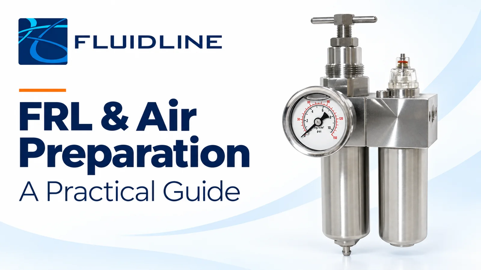
The right air-preparation arrangement delivers the airflow, pressure and air quality that downstream equipment needs. Start with the application, then select the filter, regulator and—only where required—lubricator. Matching the pipe connection alone is not enough.
This Fluidline practical guide explains what to check when specifying an FRL unit or filter-regulator for pneumatic tools, actuators, machinery and instrument-air systems in Zambia.
What does an FRL do?
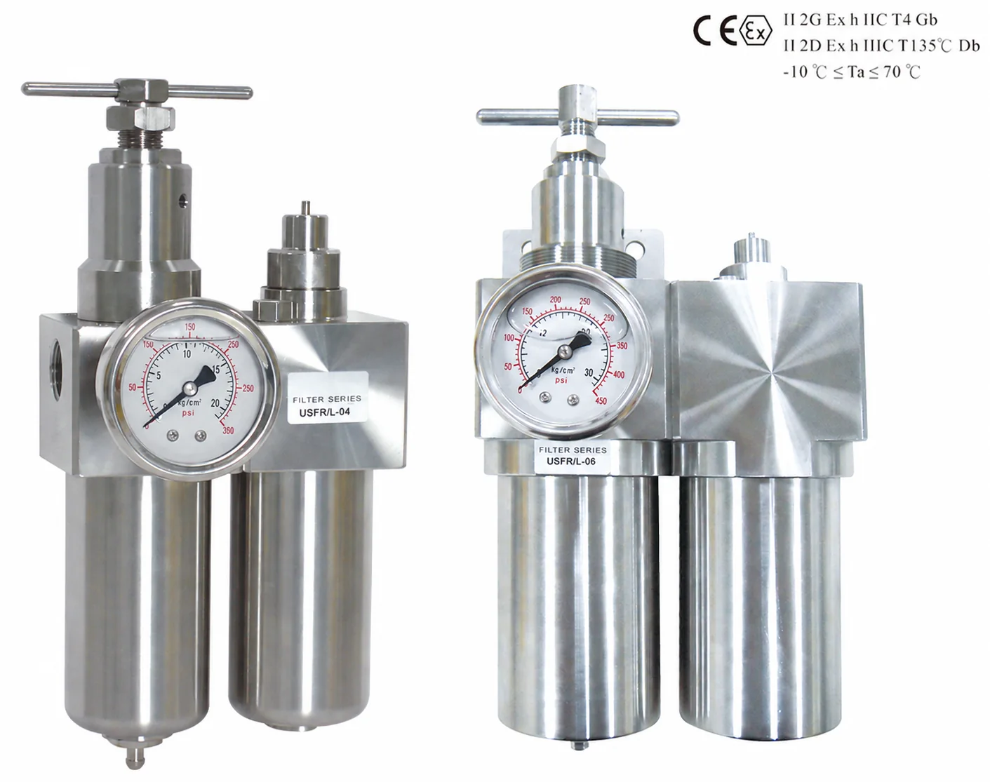
FRL stands for filter, regulator and lubricator. The functions may be supplied as separate modules or combined into a compact assembly. A filter-regulator combines filtration and pressure regulation; adding a lubricator is a separate application decision.
| Component | Its purpose | Selection check |
|---|---|---|
| Filter | Removes specified contaminants. A general-purpose unit typically separates liquid condensate and captures particles. | Required filtration performance, airflow, drain type and downstream air-quality requirement. |
| Regulator | Reduces supply pressure and controls downstream pressure within its operating characteristics. | Inlet pressure range, outlet setting, flow capacity and acceptable pressure variation. |
| Lubricator | Adds a controlled amount of suitable oil to the air where downstream equipment requires it. | Whether lubrication is permitted or required, oil specification and effective operating flow range. |
1. Establish the airflow required during operation
Record which devices run together and their peak demand, not just average air consumption. Several cylinders moving simultaneously can create a different requirement from one device operating on its own. Include the intended duty cycle and any planned expansion.
Compare the assembly’s published flow characteristics at your actual inlet and outlet pressures and the pressure drop you can accept. A catalogue flow figure is meaningful only with its stated test conditions. Confirm whether quoted litres per minute refer to normalised or standard reference conditions, or actual compressed volume; values using different reference conditions need conversion before comparison.
Practical check: if a machine performs properly at rest but slows during simultaneous movements, investigate pressure and flow during that operating cycle. Do not assume the compressor pressure reading describes conditions at the machine.
2. Check inlet pressure, outlet pressure and pressure drop
Specify the lowest available inlet pressure during demand as well as the highest possible supply pressure. Then identify the pressure required at the equipment. The unit must remain within its pressure and temperature limits while delivering the necessary flow.
A regulator cannot increase pressure above its supply. Outlet pressure can also fall as demand increases, according to the regulator’s flow characteristics. Allow for losses through filters, valves, fittings, hoses and tubing between the supply and the point of use.
Check the regulating range, gauge range and whether a relieving or non-relieving design is appropriate. A relieving regulator can vent excess downstream pressure under its designed conditions; it is not automatically a safety relief device or a means of isolating equipment for maintenance.
3. Match filtration and drying to the application
40-micron filtration is standard for the applicable Fluidline filtered ranges; 5-micron filtration is optional. Confirm the selected model and filtration element with FSZ.
Define the acceptable particle, water and oil contamination at the equipment. If the project specifies an ISO 8573-1 air-purity class, provide the complete requirement rather than describing the air simply as “clean”. A filter’s micron rating alone does not define the complete air quality.
A general-purpose filter, coalescing filter and dryer perform different duties. A coalescing stage can remove specified fine liquid aerosols; drying addresses water vapour and the required pressure dew point. A standard FRL does not automatically remove water vapour or oil vapour.
Use an appropriate sequence of treatment stages for the required result. Avoid adding finer filtration without checking its capacity, pressure loss and servicing needs. Also consider the coldest conditions along the air route: moisture can condense downstream if the air is not dry enough.
4. Choose a drain arrangement that will be maintained
Collected condensate must leave the filter bowl reliably. A manual drain needs access and a scheduled check. An automatic drain can suit unattended or less accessible equipment, but its operating pressure, installation requirements and discharge arrangement still need checking.
Do not treat “semi-automatic” and “automatic” as interchangeable descriptions. Some designs drain when pressure is released; others respond to the collected liquid level. Confirm how the selected drain operates on a continuously pressurised line.
Provide a suitable route for condensate discharge and follow the site’s collection and disposal procedure. A blocked drain or overfilled bowl can undermine otherwise suitable air preparation.
5. Add lubrication only when the equipment requires it
Check the downstream equipment instructions before adding an airline lubricator. Some pneumatic tools and devices require oil in the air; other equipment is intended for unlubricated operation or has restrictions on oil contamination.
Where lubrication is required, confirm the approved oil, lubricator type, minimum effective airflow, delivery distance and adjustment method. Do not assume an arbitrary drip rate suits every tool or duty cycle.
Keep lubricated branches separate from instruments or processes that require unlubricated air. If a system has already operated with added lubrication, check the equipment requirements before stopping it; some components require continued lubrication once it has been introduced.
6. Check connections, materials and installation space
Confirm the exact thread standard and size, mounting method and flow direction. Two units with the same nominal port size can have different capacities and pressure losses. Select for performance first, then verify the connection arrangement.
Review the bowl, body and seal materials against pressure, temperature, chemicals, cleaning agents and the surrounding environment. A transparent bowl is useful for inspection but must be compatible with the conditions. Use the specified guards and protection where required.
Allow room to read the gauge, adjust the regulator, drain the bowl and replace the element. Check the required mounting orientation. Provide suitable isolation and depressurisation, and assess whether the machine needs additional controlled pressurisation or exhaust functions.
7. Treat preparation and air distribution as one system
A correctly selected service unit can still be limited by a restrictive coupling, undersized tubing or a long hose run. Review the route to the equipment and check for leakage as part of commissioning and maintenance.
Where several branches need different pressures or air qualities, consider their individual preparation requirements. An air header manifold distributes air to multiple outlets; it does not replace the filtration, drying or regulation specified for each application.
Maintain the performance you selected
Establish a service schedule suited to contamination, duty and the selected unit’s instructions. Check drainage, bowl condition, leakage, gauge behaviour and filter condition. Investigate an increasing pressure drop rather than repeatedly raising the pressure setting to compensate.
Before opening bowls or servicing components, isolate the supply, release stored pressure and verify the equipment is safe under the site’s procedure. Use the specified replacement parts and compatible cleaning methods.
What to send Fluidline for a quotation
Send the information below so Fluidline can assess an appropriate arrangement and confirm the proposed specification.
- Application: equipment served, process and whether it is a new installation or replacement.
- Airflow: peak simultaneous demand, duty cycle and the units/reference conditions used.
- Pressure: minimum and maximum inlet pressure, required outlet pressure and allowable pressure drop.
- Air quality: particle, moisture and oil limits; required dew point or specified purity class.
- Connections: thread type, port size, existing tubing or hose and available installation space.
- Operating environment: air and ambient temperatures, exposure and material requirements.
- Configuration: filter-regulator or separate modules, drain preference, and whether lubrication is required.
- Accessories: gauge, bracket, isolation, exhaust or controlled pressurisation requirements.
- Order details: quantity, delivery destination, timing and documentation requirements.
- For replacements: clear photographs, the existing part number and any available datasheet or drawing.
Email ram@fluidline.co.zm or brett@fluidline.co.zm, or call +260 977 457 198. Fluidline Solutions Zambia Limited is based at Plot 1886B, Fourth Street, Ibex Hill, Lusaka, Zambia.
Frequently asked questions
Do all pneumatic systems need a complete FRL?
No. Select the functions the application requires. A filter-regulator may be appropriate where added lubrication is unnecessary, while other systems need additional treatment stages.
Can I select an FRL by its port size?
Port size is only one check. Verify capacity at the relevant pressure conditions, acceptable pressure loss, filtration, materials and the requirements of the downstream equipment.
Will an FRL replace a compressed-air dryer?
No. Separating liquid water is different from reducing water vapour. Determine the required dew point and select drying equipment where the application needs it.
Why does the gauge look correct but the machine still slows down?
A static reading may change under load. Check pressure at the equipment during operation and investigate demand, restrictions, leakage, filter condition and the available supply.
Is finer filtration always better?
Specify the air quality needed by the equipment. Any additional filtration stage must be correctly sized and maintained; a finer element alone does not guarantee a better-performing system.
Related Fluidline resources
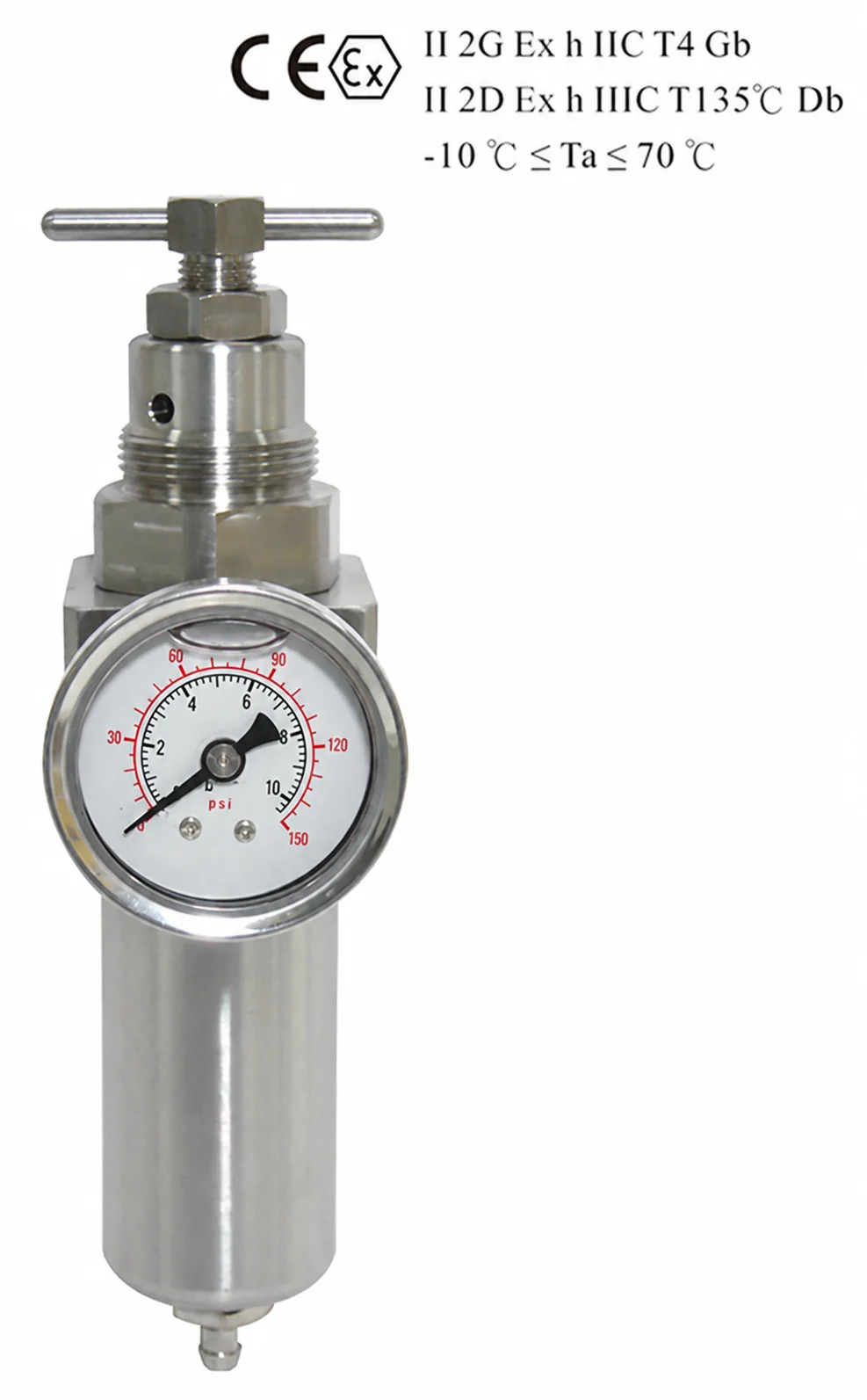
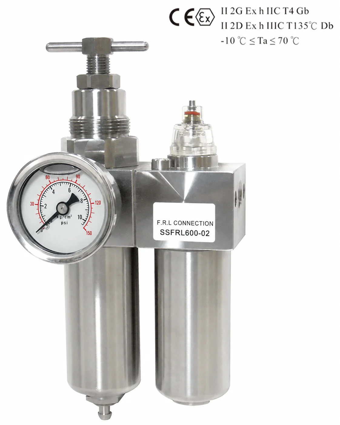
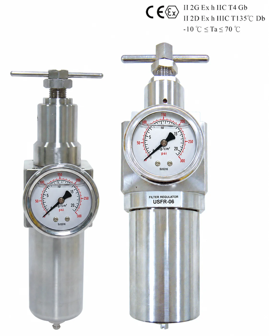
Air Preparation Products from Fluidline
Discuss Your Zambia Requirement with FSZ
Contact Fluidline Solutions Zambia Limited at Plot 1886B, Fourth Street, Ibex Hill, Lusaka. Email Marisa@fluidline.co.zm or call Boniface on +260 977 457 198. The FSZ team coordinates product selection, current availability, documentation and delivery for your Zambian project.